
After several days since my last article on my Z80-based home-brew computer I came back to talk about my experiences during this journey back to the old 8-bits days. This article will show you how I was able to communicate between my little computer and my Mac using a serial communication over an USB line. To do this I had to find a Z80 SIO (Serial Input/Output) periphery, a chip of the big Z80 family expressly developed for serial communications. I also bought a USB-to-serial converter module based on the evergreen FT232 chip from FTDI, needed not only to drive RX/TX signals but also the serial handshaking signals (like CTS) used to synchronize the transmissions between local and remote device.
The Z80 SIO is part of the Z80 family, so it shares with the other members of this line the control lines that allow the chips to be wired to the Z80 CPU and to each other with no external components. Like the PIO, that we used in a previous test, the SIO is a chip dedicated to the data exchange with the external world: unlike the PIO, however, the SIO uses a serial protocol. In a parallel protocol data is presented on complementing lines: each line carries a single bit, and by reading from or writing to those lines the protocol carries the information between the client device and the remote server. Remember the LEDs? They were turned on/off by passing a byte at a glance. However, in a serial interface the single bits of the information are sent sequentially, one by one, on a single line. This permits to reduce the wirings needed to connect the sender and the receiver, although it requires more work to exchange such information because the sender has to “disassemble” the byte into its single bits, and the receiver also has to “reassemble” these bits in a byte. Moreover, there are several other signals that the SIO has to manage because this integrated was born to connect a local terminal to a remote computer via a modem, signals that were used as handshakes to synchronize the trasmissions. For our purposes we only need a few lines because the USB is a modern and more highly efficient version of the old serial ports: beside the RX and TX lines, obviously needed because they carry the data exchanged between the systems, we’ll use only another output line from the SIO, the RTS pin. RTS stands for “Request To Send” and it’s sent by a device that would start a transmission. It’s like an alert sent to the receiver to inform it that the sender is ready to send data. This was useful with the first modems, that were half-duplex, meaning that they couldn’t send and receive at the same time, so this mechanism was develped to act as a traffic light, to set which device had to send data and whch one had to recceive them.
Now, we need to wire the SIO to the LM80C. Before to star wiring, I would like to spend a couple of words about the SIO versions available. Three different versions of the SIO exist (at least, when we talk about DIL packages, but this is our case): SIO/0, SIO/1, and SIO/2. They just differ each other for a different pinout. Since the DIL package of the chip has only 40 pins, there is not enough space to bring out every internal signal of the device, so engineers made some bonding choises and bonded some signals together, to accomodate different user requirements. For our purposes, these versions are the same: personally, I used a SIO/0 because I found this one.
Let’s start wiring the chip. We need to connect
- pins D7..D0 to the data bus;
- M1, /IORQ, /RD, /INT and CLK to the corresponding pins of the CPU;
- C/D and B/A are used to select the command/data mode and the serial B/serial A port (forgot to mention that the SIO has 2 serial ports? Yes, it has, so you can use a single SIO to create 2 serial lines, i.e. connect the SIO to another serial periphery and to an host computer too). Wire them to A1 and A0, respectively (i explain the functions of these connections in another part of this article);
- IEI and IEO are used to insert the chip into the interrupt daisy chain of the Z80 family: personally, I chose to set the SIO as the higher priority device in the daisy chain, followed by the CTC and the PIO, in the last position. The position in the interrupt daisy chain is important to set its priority: the higher the priority is the sooner the interrupt will be serviced. I considered that the receive of a character from the serial line was more important than the signal given by the CTC to update a counter. To accomplish this, just connect IEI to +5V through a 10K resistor and IEO to the IEI pin of the CTC; then, connect the IEO pin of the CTC to the IEI pin of the PIO.
- VCC and GND to 5V and ground, respectively (don’t forget the decoupling capacitor, too).
Now we have to face up with a couple of problems. The first one to be solved is how to select (i.e., enable) the chip. This is easy to solve, since we have a couple of unconnected outputs in the 74139 address decoder we can use it to select the SIO. So, let’s connect the Y2 line (pin 10) of the 74139 to the /CE pin of the SIO. We also have to do another modify to the previous circuit that we set up when we added the CTC: the pin no. 14 of the 74139 has to be disconnected from ground and instead connected to pin A5 of the CPU. Doing so, we can select the SIO periphery during an I/O operation just by setting A5 and A4 to 1 and 0, respectively. The second problem is more complicated. The SIO uses 2 different clocks: one is the system clock that it’s used internally by the chip for classical timing purposes, while the other one is used to synchronize the RX and TX channels. This clock affects directly the baud rate of the serial ports. In every Z80 manual it is suggested to use the CTC to provide such clock so that it’s possible to change the serial speed by software, simply changing the frequency of the sync signal generated by the CTC. The SIO can set a prescaler to divide the serial clock by a factor of 1, 16, 32, and 64. The baud rate is tied up to specific clock speeds: one of these is 1,843,200 Hz. Did you remember that, at the beginning of our journey in the 8-bit days, we chose a specific clock for our computer, 3,686,400 Hz? In fact, 3,686,400 Hz is exactly twice the base frequency mentioned above. So at first glance this seems a problem that can be solved easily: we could choose the 1x prescaler and the connect the system clock to the transmitter/receiver clock pins. Let me say immediately that this solutions WON’T work! This is because the TX/RX clocks must be at least 16x the baud rate. Someone could think that the solution is to use the CTC to obtain the 3,686,400/16=230,400 Hz signal needed to feed up the TX/RX clock pins. Another error! We can not do this because the timers of the CTC accept only input clocks with a maximum frequency that is half the system clock: in our case, this means a clock of 3,686,400/2=1,843,200 Hz. The solution is to add another D-type flip-flop and use it to halve the frequency of the system clock, as we already did with the original frequency of 7.37 MHz of the crystal quartz we are using. Again, we can not use this signal to clock the timer because it’s externally: so we’ll use the 1.84 MHz clock as an input clock of one of the units of the CTC. Every unit of the CTC can operate both in timer and in counter mode. The latter simply does what its name means: it counts events happening on its input pin. So we’ll wire the D-type FF output to the trigger pin of timer/counter 0 of the CTC and count a certain amount of impulses to generate the 230,400 frequency clock needed for the TX/RX clock pins of the SIO. But how many impulses do we have to count? First, we have to choose the speed of the serial line that we intend to set up between the Z80 and our computer; second, we set the CTC to generate such clock.
I assumed that a good compromise between speed, reliability and compatibility was 19,200 bps (bauds per second). So, since the TX/RX clock must be at least 16 times the baud rate, we need a TX/RX clock of 19,200 x 16 = 307,200 Hz. By having an input clock on the trigger pin of the CTC of 1,843,200 Hz, to obtain the 307,200 Hz clock the CTC has to count 1,843,200 / 307,200 = 6 clock impulses. So we set the starting value of the internal register to 6 and set the unit to run in counter mode: each impulse on the trigger pin will decrement the contents of the counter register. As you remember, the CTC automatically sends a low signal on the output pin TOx of the corresponding timer/counter unit as soon as the internal register reaches 0. By doing so, we have set a system to get specific baud rates that we can adjust by software, if we want to change the serial speed in a future moment.
We are close to the finish lane. Before to try the serial communication, we need to wire up the FT232 module. We’ll use the serial port A of the SIO, so refer to the schematics below to find the corresponding pins:
- connect TX pin from FT232 to RX pin of the serial port A of the SIO;
- similarly, connect RX pin of FT232 to TX pin of SIO port A (obviously we have to cross-wire the RX/TX lines because the RX line of the sender is the TX line of the receivers, and vice-versa);
- connect CTS line from FT232 to RTS pin of SIO port A (this signal is sent by the SIO to the remote device to advert that it wants to start a transmission);
- lastly, connect GND of FT232 to GND of the circuit.
CAUTION! DON’T connect the 5V pin that comes from the FT232 module to the 5V line of the computer unless you intend to power the LM80C computer through the FT232. If the LM80C computer has already a power supply of its own, leave the VCC line of the FT232 module unconnected.
If you look at the schematics below you’l see that I’ve added some resistors on the RX/TX/CTS lines that come from the FT232 module: this is done in order to limit the current between the module and the LM80C when 2 different power supplies are used. In fact, if you power up the LM80C before to connect the FT232 to the PC you’ll see that some current flows through the wirings, that will turn up the light of the serial module: this is devastating for the integrated circuits! Never send signals to the pins of an unpowered chip.
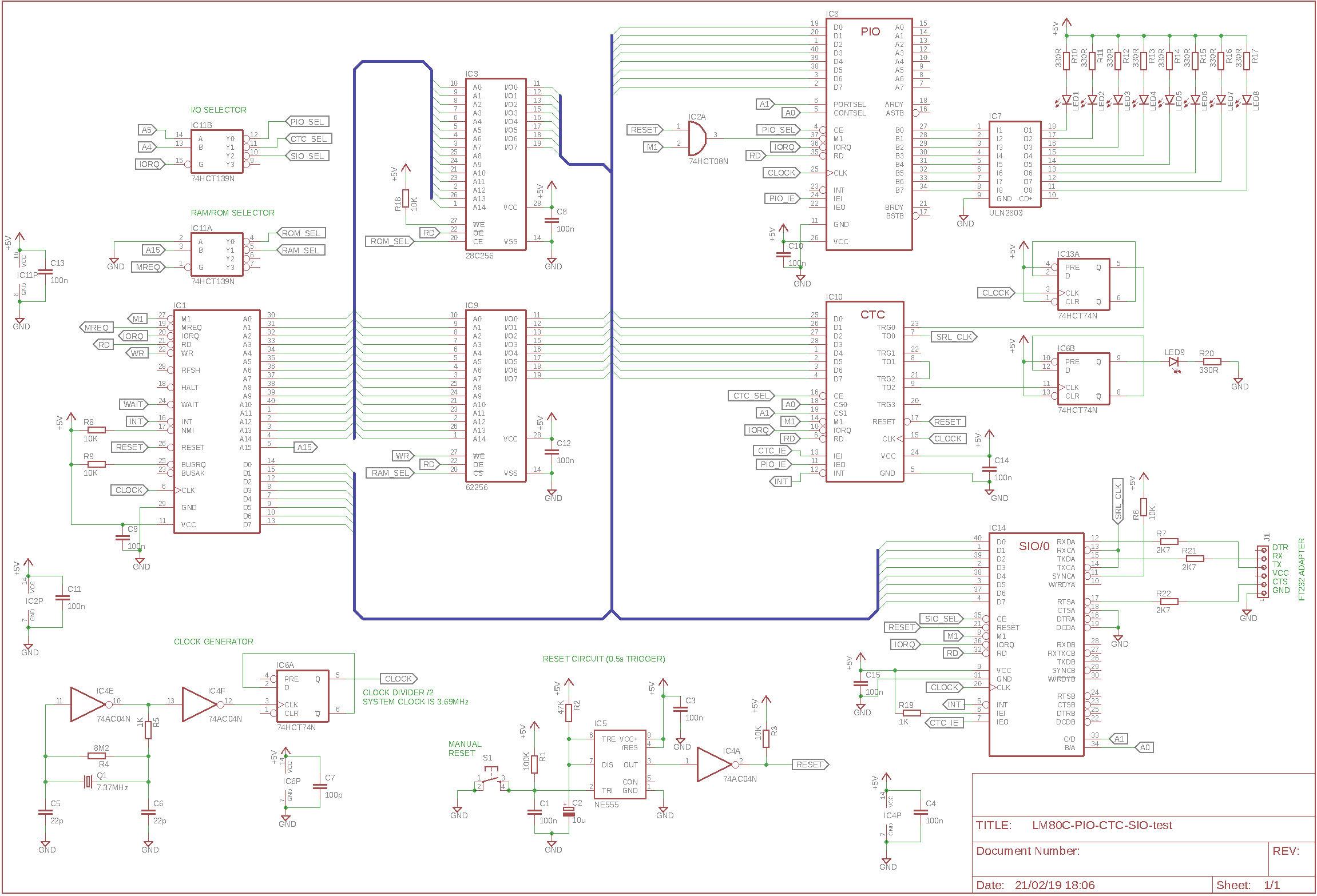
LM80C & Z80 SIO: schematics
There are some little things to do yet. Since we are using the SIO to communicate with a simplified serial line represented by our USB adapter, most of the handshaking signals used for modem transmissions are useless for our purposes: so we need to pull-up the SYNCA pin with a 10K resistor and to connect to ground CTCA and DCDA pins (they are used to activate the serial receiver: but we want our receive to be always active). This is a picture of my prototype assembled on breadboards: on the left you can see the FT232 module.
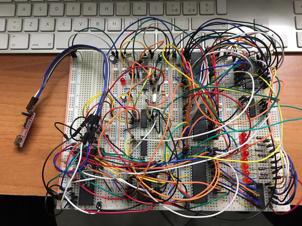
LM80C SIO serial communication
The hardware is ready. Now we need the software. Our program is an evolution of the one used to test interrupts with the CTC: we have added a portion of code to set up the SIO and the interrupt routines that receive available characters sent to the LM80C by the host computer. To try the communication, just connect the FT232 module to the host computer, then runs a serial terminal emulator of your liking (I used CoolTerm on my Mac but there are a lot of software you can choose from) and set the serial port for a speed of 19,200 bps and 8N1 as options: this means 8 bits for data, no parity bit, 1 stop bit, the same settings used for the SIO configuration (look at the code). Then try to digit some letters and you’ll see that the LM80C echoes the pressed keys back to the serial emulator. This works because the SIO is set in a manner that it raises an interrupt each time a character has been received. The CPU recognizes this interrupt (thanks to the fact that the SIO is into the interrupt daisy chain structure) and handles the corresponding interrupt service routine. The character is picked up from the SIO input buffer and echoed back to the host computer. Thanks to the fact that the serial interface is interrupt driven, the CPU still continues to execute the main code, without any apparent stop caused by the serial communication, as you can see looking at the LEDs that continue to binary-count. Another advice that the Z80 is receiving the characters is given by the 2 most significant output pins of the PIO that are turned on/off as soon as a new character is available from the SIO.
A special mention goes to Mario Blunk: it has written a very good tutorial on how to program the Z80 peripheral devices, that I used to get the base code of the Z80 chips.
Code and schematics are available on this repository from GitHub.