
Today I had an idea, I thinked that a timer was wasted to just blink a LED. Why didn’t we use it for what it has been designed for? It’s a timer, it’s built to measure time. It can raise interrupts, too. So why not combine the two things? Realize an interrupt-driven software timer, a piece of software that increments a counter every second but without interfering with the main code. In fact, an interrupt can stop the code of the user and force the CPU to execute another portion of code. When it’s have finished, the CPU can resume the interrupted work, thus the name “interrupt”.
Interrupts are a fondamental part of every system: by honoring an interrupt, the CPU will suspend the code that was executing, save the pointer of the instruction following the last one it executed, then it jumps to execute some code stored in a particular portion of the memory. When this code is finished, it resumes the execution of the interrupted code by recovering the pointer it has saved previously. Interrupts are used to interrupt the main code when a special event occurs, an event so important that the CPU shouldn’t ignore it: think about an user that presses some keys over a keyboard. It is fundamental that the system collects each key that has been pressed, even if the CPU is doing something else. Look at this scenario: the user presses a key, the peripheral that manages the keyboard raises an interrupt, alerting the CPU that something that needs its attention has happened. The CPU halts the current task, receives the code of the key, stores it into a temporary buffer, then resumes the task is was executing. Everything in a manner that is completely trasparent to the end user, that thinks that the CPU is giving its full attention to him/her. When the CPU will execute the portion of the system code that reads the user input, it will recover the buffered keys, giving the user the impression that it was the task of that moment.
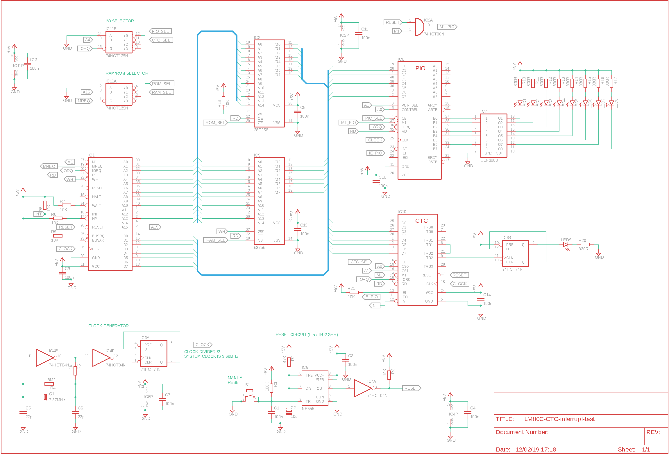
The circuit to manage an interrupt of the CTC is almost done, we ony have to make some changes in order to get the CPU work properly:
- connect the /INT pins of CTC and CPU
- put a 10K pull-up resistor between +5V and IEI pin
- a minor change is connecting the IEO pin of CTC to the IEI pin of PIO: this one will be useful later, when we will have other peripherals that will raise interrupts, too.
From the software side we only have to make little changes: first, we have to activate the interrupt on the timer 2 of the CTC so that every time that its internal counter reaches zero not only it send a signal on its output pin but raises an interrupt, too. Second, we have to set the vector of the corresponding interrupt routine: this is done by pre-storing the most significant bits of the vector inside the CTC registers. The less significant bits will be added by the CTC itself and will point to the timer that raised the interrupt. So we will have the CTC that sends the interrupt vector to the CPU that is composed by a part that identifies the peripheral (in this case the CTC) plus another part that identifies the timer that raised the interrupt. Third, we must set the interrupt mode 2 on the CPU. This is a very powerful mode: when an interrupt is raised, the CPU receives the interrupt vector that point to the interrupt routine to be executed directly by the peripheral that raised the interrupt and directly on the data bus. It ony has to get this address (in a completely automatic process) and then jumps to the location of the memory pointed by the vector.
Our interrupt routine is very simple: it just increments the value of a RAM cell and sends it to the PIO to “display” its value through 8 LEDs connected to its parallel port.
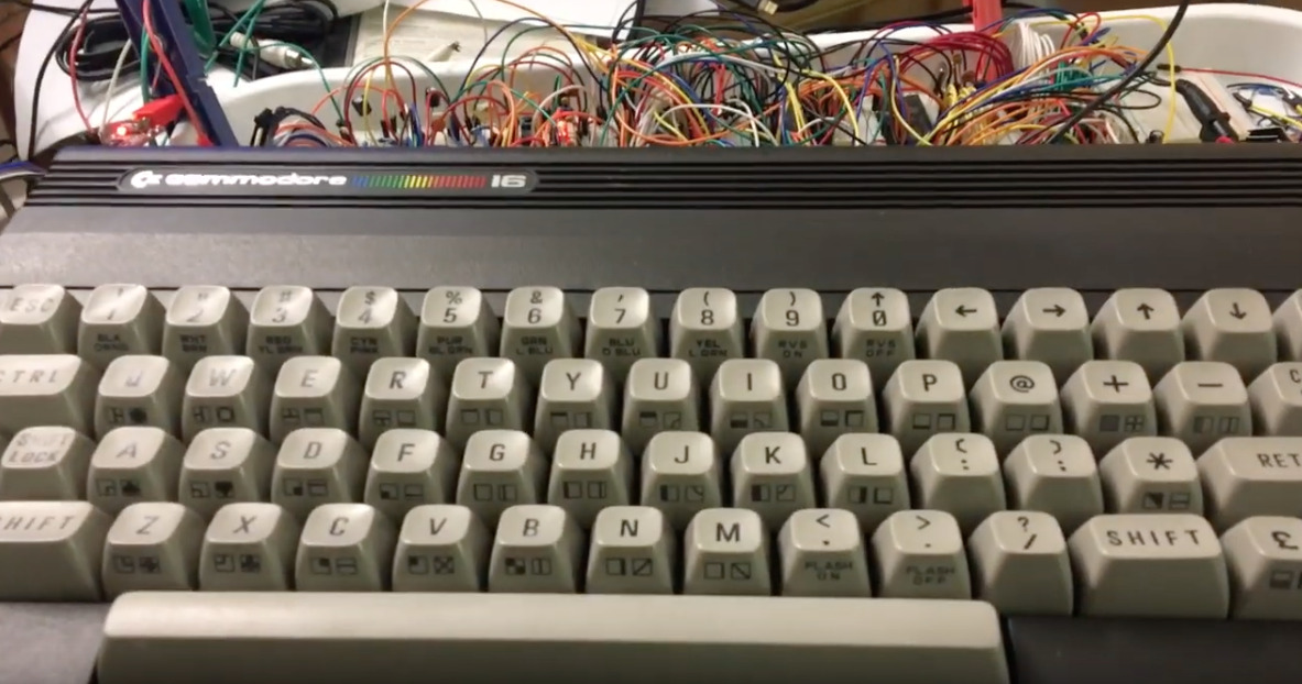
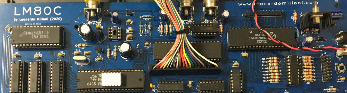
LM80C: CTC & interrupts
Here is the code in action:
Code and schematics available on my GitHub repository, as usual.