
Watchdog (Atmel Atmega328P)
In a previous article on the use of the watchdog we have seen how to use this peripheral to reset the microcontroller if the CPU gets into a dead-lock code.
With this article we’ll instead analize another use of the watchdog, namely a simple interrupt generator, that you can for example use to raise up the MCU from a power saving mode without the need to use external interrupt signals or the timers of the microcontroller.
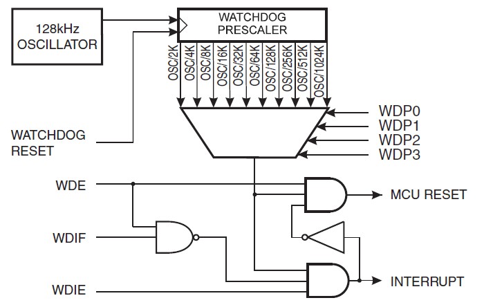
The watchdog is e peripheral that can work in several modes:
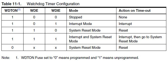 The mode we used in the past article was the “System Reset Mode”: in case an overflow of the watchdog counter occurs, a reset signal is generated. Another mode is the “Interrupt And System Reset”, that I’ve used in my scheduler leOS2: the first time that the counter overflows, an interrupt is raised; the second time, if the corresponding flag hasn’t been cleared, the microcontroller will be reset. The last mode, that we’ll use below, is called “Interrupt Mode”: the watchdog simply raises an interrupt signal when its counter reach the maximum value and rolls back to zero (a way of working similar to that of the timers of the MCU).
How can we use this mode? We can use it to put the chip in sleep and wake up at regular intervals, so that we can cut down the power consumption, useful if our circuit is based on a stand-alone micro (without the whole Arduino board) and it’s powered by a battery.
To do this we have to directly manipolate the microcontroller’s registers because the wdt.h library that is included into the Avr toolchain doesn’t support the “Interrupt Mode”. We just need to have the datasheet of the microcontroller we’ll use in our project: in the case of the Arduino UNO, we’ll get the sheet of the Atmega328P. The datasheet reminds us (page 50) that in order to modify the WDTCSR register (that controls the watchdog) we have to do a couple of things in a particular order: first, we have to set (put to 1) 2 bits (WDCE e WDE) and then, in the next 4 clock cycles, we have to set the bits as needed. This sort of “security system” is necessary to avoid to write in the register random values that could lead the microcontroller to infinite resets.
We’ll also use the sleep.h library to manage the power saving modes: this is another library of the Avr toolchain. The following sketch toggles the status of the built-in LED of the Arduino UNO every x seconds (the user can set the interval). The microcontroller will be in power down mode for the most part of the time, a deep sleep mode that can permit to have the maximum power save. To increase the power saving, we have also included the power.h library, used to power off all the unused peripherals. Looking at the sketch, you can see that I disabled all the peripheral: it will be the user that will have to leave the used peripherals on.
#include <avr/wdt.h>
#include <avr/sleep.h>
#include <avr/power.h>
const byte LED13 = 13;
byte ledStatus = 1;
volatile unsigned int counter = 0;
volatile byte flag = 0;
void setup() {
   MCUSR = 0; //reset the status register of the MCU
   wdt_disable(); //disable the watchdog
   pinMode(LED13, OUTPUT); //pin 13 in OUTPUT
   digitalWrite(LED13, ledStatus); //LED on initially
   setWdt(); //set up the watchdog
   //set up the sleep
   set_sleep_mode(SLEEP_MODE_PWR_DOWN); //sleep mode - POWER DOWN
}
void loop() {
   power_all_disable();
   sleep_mode(); //CPU in sleep-this corresponds to sleep_enable+sleep_cpu+sleep_disable
   power_all_enable();
   if (flag) {
      wdt_disable();
      counter = 0;
      flag = 0;
      //other things to do can be put here
      ledStatus ^= 1; //toggle the LED
      digitalWrite(LED13, ledStatus);
      setWdt(); //re-set the watchdog
   }
}
void setWdt() {
   SREG &= ~(1<<SREG_I); //disable global interrupts
   //prepare the watchdog's register
   WDTCSR |= ((1<<WDCE) | (1<<WDE));
   //set the "Interrupt Mode" with a timeout of 1 sec
   WDTCSR = ((1<<WDIE)| (1<<WDP2) | (1<<WDP1));
   SREG |= (1<<SREG_I); //re-enable global interrupts
}
ISR(WDT_vect) {
   if (++counter >= 1) { //set here the # of seconds for the timeout
      flag = 1;
   }
}
The code is very simple and commented. Into the setup we first disable the watchdog (this is done for security reasons, in the case we did something incorrect in the rest of the code, to avoid auto-resets), then we set the sleep and the power saving mode. The main instruction of the loop routine is sleep_mode, that puts the micro in sleep, waiting for the interrupt to wake it up. When the watchdog will raise the interrupt, the CPU will be woken up and will execute the corresponding ISR that increments the overflows’ counter. Then into the loop we check if the desired number of seconds has passed, in this case we execute our job (this sketch simply blinks a LED), and finally it repeats the loop.
[notice]
Note for the Arduino MEGA/MEGA2560 users: the original bootloader of these boards doesn’t disable the watchdog after a reset, leading to infinite resets. If you own a board of these you have to flash the new bootloader that fixes this issue: it can be dowloaded from here. This mod is necessary because the watchdog must be disabled as soon as the MCU has been powered: the execution of the code of the bootloader is an operation that is long enough to avoid to reach in time the instructions of the sketch that disable the watchdog, so the board will drop into the hole of the infinite loops.
[/notice]