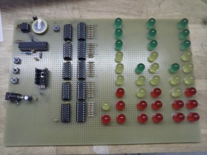
This is the LED clock, a LED wall clock that visualizes the time dividing the LEDs into columns that represent the ten’s/units of hours, minutes, and seconds. Compared to those binary clocks widely available, this is simpler to read.
The clock uses an ATmega328P and a PCF8563 as external RTC. It drives the LEDs with no multiplexing so the LEDs are brighter. The LEDs are 10 mm in size to facilitate their seeing. The circuit can regulate its luminosity depending on the ambient light of the room in which it is used.
Hardware
The heart of the circuit is an ATmega328P powered at 5V and clocked with the 8 MHz internal oscillator (I’ve decided not to use the external crystal because I didn’t need a lot of clock speed and to reduce the components). The MCU drives the LEDs using 5 74HC595 shift registers connected to 5 Darlingthon array ULN2803. In this way I can light the LED without multiplexing, that usually reduces the brightness of the LEDs. The current is provided by a PNP BDX54 transistor: using the PWM, I can modify the brightness of the LEDs too. This functionality is used to set the luminosity of the matrix with the photoresistor to adapt it to the ambient light (more darkness = less brightness).
The external power supply should provide at least 1 A of current, but it’s better it it can provide more (I’ve choosen a model that provides 2.5A of current). All the LEDs require about 550 mA (~14 mA/LED), plus the current sinked by the rest of the circuit.
I’ve choosen a PCF8563 like RTC, with a CR2032 backup battery that should guarantee at least 8/10 years of autonomy in case the circuit will not be powered up. Thanks to the 2 diodes I used, the battery will only power the RTC when the external source is disconnected.
Software
To compile the sketch you need some additional libraries:
PinChangeInt
Rtc_Pfc8563
leOS2
The firmware is compiled for a standalong Atmel ATmega328P (it should work on an ATmega168P too, because it only takes ~9kB of Flash memory and 445 bytes of SRAM [statically]) clocked at 8 MHz (no ext. crystal). To do that, set a micro with the following fuses:
low fuses=0xE2
high fuses=0xDE
extended fuses=0x05
When the clock is started, it checks if the RTC is running. If it doesn’t, it sets the time at 00:00:00. To program the clock you just have to press the SET button and hold it down for more than 1.5 seconds. The clock will then flash up all the LEDs to inform the user that it entered into the programming mode. Now you can set the time in this order: hours, minutes, and then seconds. To set their value, you have to press the INC/DEC button respectively to increment/decrement the value. The clock will only show the current value that is being set (hours, or minutes, or seconds). Keep in mind that if you don’t see any lighted LED, it is because the clock is showing the value “0” ;-). To confirm your choise, press the SET button. If you don’t press any button for 10 seconds, the operation will timeout and the clock will pass to the next value, until it will reach the end of the operation (after 30 seconds). At the end of the programming mode, the clock will store the current time into 3 local registers and into the external RTC. Remembder that the clock will only load the time from the external RTC 1 time per hour, and will update the time using a PCINT interrupt attached to the CLK_OUT pin of the RTC.
In normal operation mode, the INC and DEC buttons have 2 more functions, that you can activate by pressing and holding them down for more than 1.5 seconds. The INC button activates/deactivated the function that modify the LEDs luminosity depending on the ambient light (more ambient light =
more LEDs light). The DEC button activates/deactivates the “night mode”: the clock will light off between 00:00:00 and 05:59:59. Two flashes of all the LEDs will indicate the activation of the night mode, one flash the deactivation of it.


