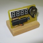
In this article I will show you the Micrologio (in english we can translate it with “Microwatch”, as Micrologio is the union of the words “Micro-” and “-logio”, with the latter that is a contraction of the word “orologio”, watch), a micro table watch based on an Atmega328P. This one differs from other similar projects seen in the web because the Micrologio has been realized to study several techniques to be used with microcontrollers: the multiplexing, to directly drive a 7-segment LED display, extreme power saving levels to pilot the watch with a little CR2032 battery, the use of the microcontroller’s Real-Time Counter (RTC) as a time-keeper module to avoid the use of an external Real-Time Clock. Thanks to all of these techniques, the Micrologio is smart, tiny, uses a limited number of electronic components and its power consumption is very low.
First of all, the components’ list:
- a stripboard to build the project
- 1x Atmel Atmega328P or, alternatively, an Atmega168P
- 1x tactile switch
- 2x 0.1uF ceramic capacitors
- 5x 47 ohm/0.25 W resistors
- 1x 22K/0.25W resistor
- 1x 32768 Hz crystal (Cl 12.5 pF)
- 2x 22pF ceramic capacitors
- 1x 7-segment red LED display with common anode (I used this: China Young Sun Led Technology Co. Ltd YSD-439AR6B-35)
- 1x CR2032 battery with its holder
- cable wire for wirings
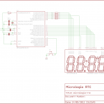
This is the schematic of the Micrologio:
Warning: the resistors on pins 23..27 are calculated to work for a voltage of 3V (provided by the CR2032): if you want to realize the Micrologio to work with a different voltage, you have to choose the proper resistor’s value.
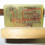
Execution: the assembly of the Micrologio on the stripboard is easy. You just have to follow the schematic and place the components in the way you like. I used AWG 30 for wirings but you can choose any kind of wire you have. Below a rear picture of the my Micrologio:
The microcontroller’s firmware is available here. It’s written with Arduino IDE 0022 (but it can be easily converted to work with Arduino IDE 1.x) and uses the PinChangeInt library. Before to flash the firmware, you have to set the fuse bits as follow:
- low fuse: $62
- high fuse: $D2
- extended fuse: $FF
These values set the microcontroller to use the internal 8 MHz RC oscillator and activate the 8x divider so the chip will work at 1 MHz clock.
Project’s analysis
The trait d’union of the Micrologio is the size and power reduction in order to obtain a compact table watch that can work for a long time even if it uses a very small battery. To reduce the numer of components I decided to drop off any external display driver and to connect the 7-segment display directly to the microcontroller’s pins. To do that I had to find a way to power the LEDs’ display without exceeding the current that the MCU can source through its pins, that Atmel suggests to be ~20mA (any pin can source a current that is higher but this is the reccomended value for safety operations). So I used multiplexing: with this technique, the code drives a single LED at a time, alternating the LEDs that are on, and using the phenomenon of the eye known as “persistence of vision” to let the observer to see the numbers in their entirety even the LEDs are lighting up in turn very quickly.
To eliminate any external RTC I used the internal Real-Time Counter of the microcontroller: this module, if it’s driven with an external 32768 Hz crystal and used with a prescaler of 128, can permit to obtain a perfect refresh rate of 1 Hz, that is a counter overflow every 1 second. We then attach an interrupt at the counter’s overflow and use that interrupt to rise up an ISR (Internet Service Routine) that update the time: every second (every overflow, because we have 1 overflow per second) we increment the seconds’ counter and then, the counters of the minutes, hours, days etc…. More over, the RTC module runs in power saving modes too so we can put the microcontroller in a sleep mode to further reduce the power consumption and simultaneously have the RTC module running.
To get the maximum power saving levels, I deactivated all the unused modules as well as lowering the clock at 1 MHz and using a voltage supply of 3V: so I shutted down the A/D converter, the SPI interface, the serial interface, the I2C module etc…
Thanks to this I was able to obtain a consumption of ~2.5mA when the MCU is active (i.e. it’s displaying the time on the display) and a very low consumption of ony ~1.5uA (microAmpere) when the MCU is in sleep mode. This can be archived due to the fact that the microcontroller wakes up only every 1 second and for a very short time, just to update the time’s variables, so the Micrologio can run for more than 10 years using a battery with a capacity of 200mAh. We can estimate that the battery will last for less than 10 years due to the fact that we can imagine that the user will use the watch to display the time at least 5/10 times a day, but surely the Micrologio will run for several years.
Version updates:
- the 0.4.2 contains a new multiplexing scheme and some bug fixes. There’s also a new programming menu with which the user can set up the time and date separately and a new sub-menu to modify a couple of clock settings (like the multiplexing scheme and the display’s timeout).


Hi, I really need your help… I have been stuck with makinga a RTC in atmega328p… I now have:
*8MHz bootloader for the internal clock
*Changed the fusebit so that the firmware is uploaded with correct fuse bits.
All I want is to just plot the time in “Serial.print”
Sounds easy, but i just cant get the hang of it…
//Best regards Samir from Sweden
Try looking at my swRTC library that has a couple of examples that “print” the time on the serial terminal.
It works for several clock speeds.
Ciao Leonardo, una domanda… Se invece di far spegnere il display dopo un tot di secondi, lo volessi tenere acceso sempre (anche a discapito della batteria, ma utilizzerei 2 stilo da 1.5) quale parte dovrei andare a modificare? Grazie, Stefano.
Va rivisto un pò tutto il loop perché il codice presuppone di mettere in sleep il chip e di attivare un interrupt per il risveglio. Dovresti eliminare tutta l’attuale funzione loop() e poi rinominare la funzione mainLoop() in loop(). A questo punto rimuovi la chiamata a clockOff(), rimuovi quindi anche la funzione stessa che non serve più, poi metti il codice presente in clockOn() dentro al setup. Rimuovi tutte le chiamate a clockOn/clockOff che trovi a giro. Elimina tutta la parte relativa agli interrupt e poi… prova 🙂
Ciao, grazie per la risposta. Mi puoi aiutare tu? Non sono molto esperto con la programmazione… Scusami…
Non ho al momento il tempo necessario a fare le modifiche che ti ho illustrato. Sto terminando un progetto che mi occupa tutto quel poco di tempo libero che ho. Forse in un futuro rilascerò una versione modificata del Micrologio per funzionare con un’alimentazione a batteria ma ora non ce la faccio proprio.
Ciao,
There is long time I search some that . Thanks a lot;
However, I have a question abour the accuracy drift . If I use this system outdoor ( -15°C to 50°C ) do you think I can have less than 20 min drift on a year ?
Is the drift directely by the crystal oscillator and asociate capacitor ?
Could you tell me what is the drift since you have it ?
Merci beaucoup !
Accuracy depends mainly on the environment temperature. Usually common electronics components are tested to work at 25°C.
If the temperature moves too far from this value, the components may loose accuracy. The amount is not predictable but you can try to find in the data sheets of the components (your Atmega328P and your 32 Khz crystal) how is the deviation from the reference values.
Ciao Leonardo, grazie per l’utilissimo articolo.
Ti faccio una domanda: se volessi utilizzare il tuo progetto su un MCU ATMEL 644p devo diventare pazzo nelle modifiche?
immagino che qualche registro vada cambiato (tipo PRR->PRR0 ….)
Mi interessa sapere cosa ne pensi.
Ciao e grazie ancora