
I was standing at my computer, this morning, and had nothing to do, and I was thinking about a new project. I was making the count of how many pins I needed, looking for a way to optimize their usage, just because I had to dealt with some buttons to be pressed by the user, and so a question materialized in my mind: is there a simple way to save pins when we deal with buttons? Usually externa chips are used, such as port expanders or PISO (Parallel In – Serial Out) shift registers, to manage a lot of I/O lines with few pins. But, what about if I would do the same thing without buying such devices, just with the components that usually are in the drawer? The solution that I suggest is as simple as ordinary: with just 2 pins I will able to read 3 buttons.
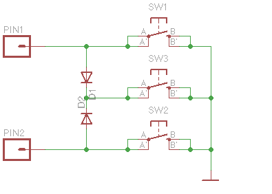
Have you ever heard about charlieplexing? It’s a technique to drive a lot of LEDs using relatively few pin just by taking advantage of the capacity of a LED to conduct current only in one direction. I turned over the problem: why do I not use a system that let me read more signals using fewer pins and some components that can conduct only in one direction? Just by using some… diodes? The diode is a semiconductor that let the current flows only from anode to cathode. If I use to diodes by connecting their cathodes, the current will only flow to the common node, it won’t be able to keep other ways. So, i.e., if I have 2 pins that I set to act as inputs and connected with 2 diodes put in the above way, if I connect the first pin to ground I will read a LOW state only on this pin because the other pin will be isulated by the diode due to the fact that its polarity is inverted. Same thing for the other pin. And what happens if I connect to ground the common node of the diodes? I will read a LOW state on both pins because they will be grounded by their respective diodes. So this idea leaded me to this schematic:
Let’s try the circuit. We need these components:
- a breadboard
- 2 diodes (common 1N4007 are good, but faster 1N4148 are valid too, as well as the 1N5819 Schottcky ones)
- 3 switch buttons for surface mounting
- wires
- an Arduino board (UNO, Leonardo)
Let’s mount the components as in the picture below (done with Fritzing):
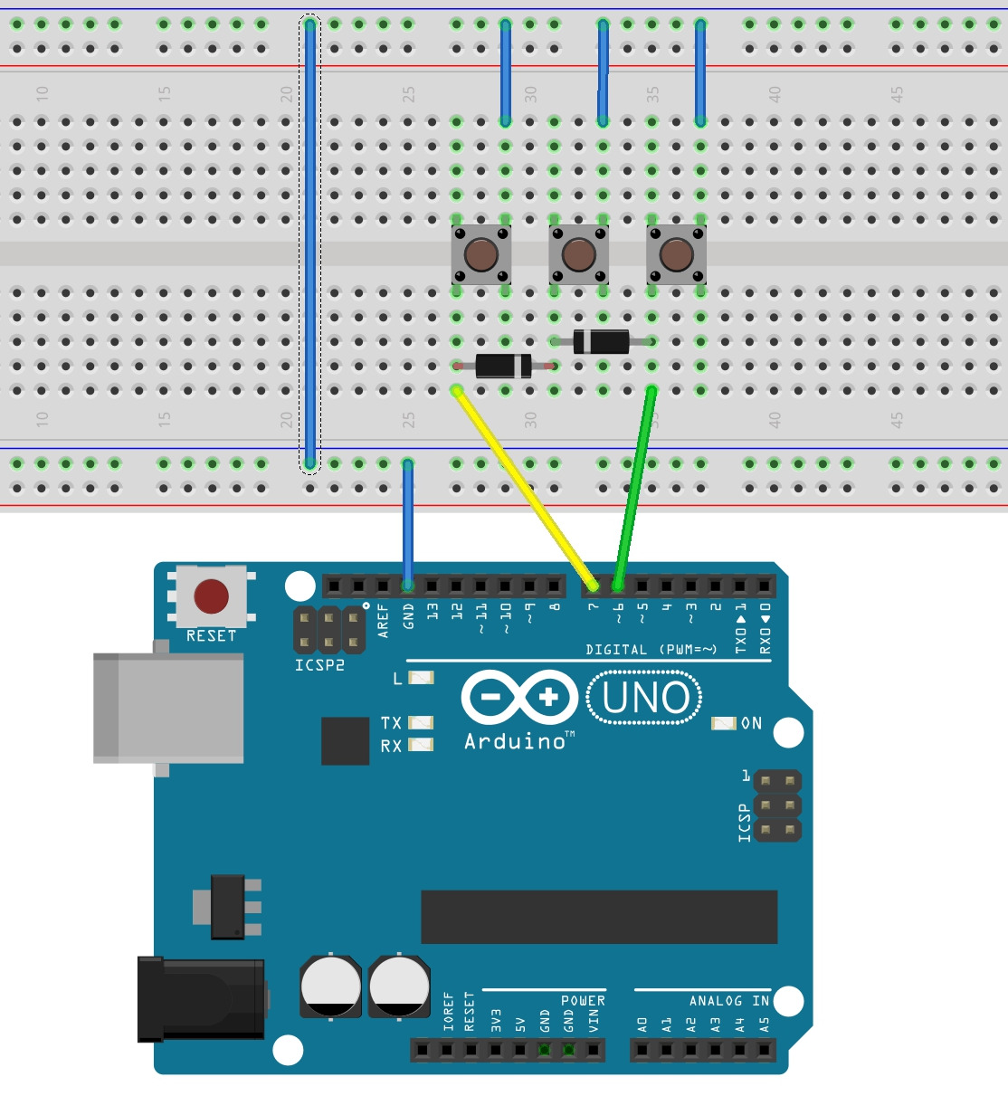
Put the 3 buttons in the middle of the breadboard, then connect their right upper pins to the upper ground line. Connect this line with the lower ground line. Connect the lower left pin of the leftmost switch to the left with the lower left pin of the midmost switch using one of the two diodes: the cathode (the side marked with a white line) to the right. Now connect the lower left pin of the rightmost pin to the lower left pin of the midmost switch using the other diode, keeping attenction to the polarity: the diode has to be mounted with the cathode facing the midmost switch, so this time the white line needs to be to the left. Connect the lower left pin of the leftmost switch to pin 7 of the Arduino board and the lower left pin of the rightmost switch to pin 6 of Arduino. The last wire needs to be put between the lower ground line of the breadboard and a GND pin of Arduino. As you can see in the picture, we didn’t use any pull-up/pull-down resistors: this was intentional because we want to use as few external components as possibile. Instead, we’ll use the internal pull-up resistors, that are present on every digital pin, to to give a specific state to this pins. Due to this choise, we need to use a function to read the pins that works with the so-called inverted logic because now, when a pin is not pressed, it will return an HIGH state, and when it’s pressed it will return a LOW state. Don’t worry about this: the function will do this for you.
Now, it’s the time to upload the code:
/* HOW TO READ 3 BUTTONS USING JUST 2 PIN
  Written by Leonardo Miliani

  Code released under the Creative Commons License
  CC-BY-SA 3.0 or any newer

  V. 1.0 - 20140826
*/

//pins declaration - use any pin you like
const byte IN1 = 6;
const byte IN2 = 7;

//setup function
void setup() {
  //setting the mode of the pins
  pinMode(IN1, INPUT_PULLUP);
  pinMode(IN2, INPUT_PULLUP);

  Serial.begin(19200); //opening the serial
  delay(2000); //a little delay to let the user open the serial monitor
  Serial.println(F("Begin"));
}

//main loop
void loop() {
  byte reading = readButtons(IN1, IN2); //read the buttons

  if (reading) { //a button has been pressed
    switch(readButtons(IN1, IN2)) {
      case 1: //button 1 pressed
        Serial.println(F("Button 1 pressed"));
        break;
      case 2: //button 2 pressed
        Serial.println(F("Button 2 pressed"));
        break;
      case 3: //button 3 pressed
        Serial.println(F("Button 3 pressed"));
        break;
    }
  }
  delay(100); //a little delay - remove if unnecessary
}

//read the buttons
byte readButtons(byte inputPin1, byte inputPin2) {
  byte response = 0;

  //I'm using the inverted logic so I do a "not" (!) to the digital read
  //then I combine the readings in a sngle bit using the 2 binary digits
  response = (((!digitalRead(inputPin1))<<1) | !digitalRead(inputPin2));
  return response;
}
How does this system work? As I already said previously, the heart of it are the 2 diodes. Normally, when buttons are not pressed, the function readButtons that read the 2 pins at which the matrix of buttons is connected to will see the 2 input lines as HIGH (or 1). But we need the inverted logic, do you remember?, because we want that a non pressed button returns a LOW (or 0) value. To do this, we’ll use the negations operator of C language, the “!”, the returns the opposite of the paramether: 0 for 1, and 1 for 0. We also put the two readings in a single couple of bits using the left shift operator (<<). The resulting value is returned by the function to the caller. When we press the leftmost switch button on the breadboard, only the pin to which it’s connected to (the pin 7 of Arduino) will be grounded, thanks to the inverted polarity of the diode that connects it to the other diode on the midmost button. Same thing when we press the rightmost button. So, in both these cases readButtons will read only one pressed button at a time. But, if we press the button in the middle things change: both diodes will conduct because directly polarized, and so both pins will be grounded.
This is the truth table of the function:
PIN1 PIN2 READING
1 0 BUTTON 1
0 1 BUTTON 2
1 1 BUTTON 3

2 Responses
[…] gestire 3 pulsanti usando solo 2 canali di entrata di Arduino (potete leggere l’articolo qui http://www.leonardomiliani.com/2014/gestire-3-pulsanti-con-2-soli-pin/ […]
[…] Mi ha molto incuriosito un articolo che spiega come poter gestire 3 pulsanti usando solo 2 canali di entrata di Arduino (potete leggere l’articolo qui http://www.leonardomiliani.com/2014/gestire-3-pulsanti-con-2-soli-pin/) […]