11 March 2023
(Italiano) Programmare con Lua – il libro
Sorry, this entry is only available in Italiano.
Official site

Sorry, this entry is only available in Italiano.
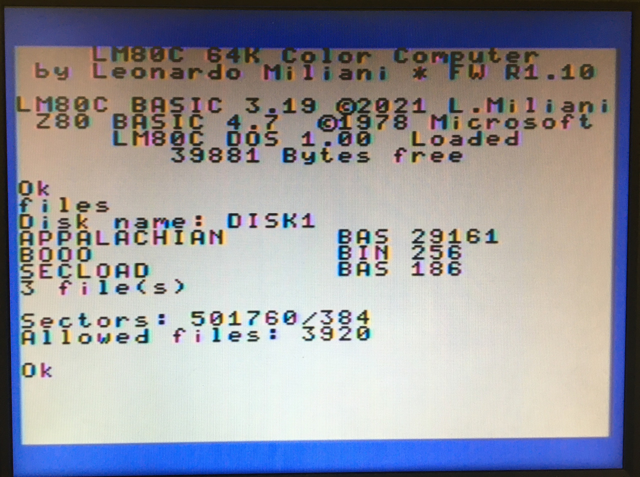
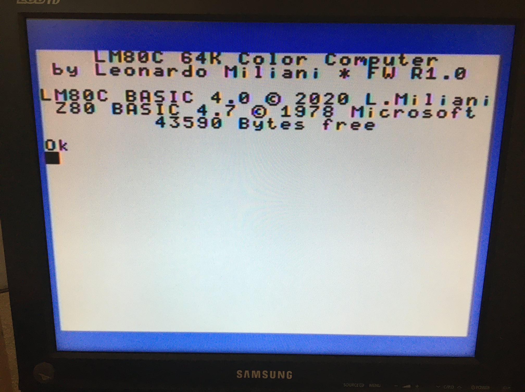
The development of my Z80 homebrew computer LM80C continues. This time the LM80C DOS 1.05 is out with newer BASIC...
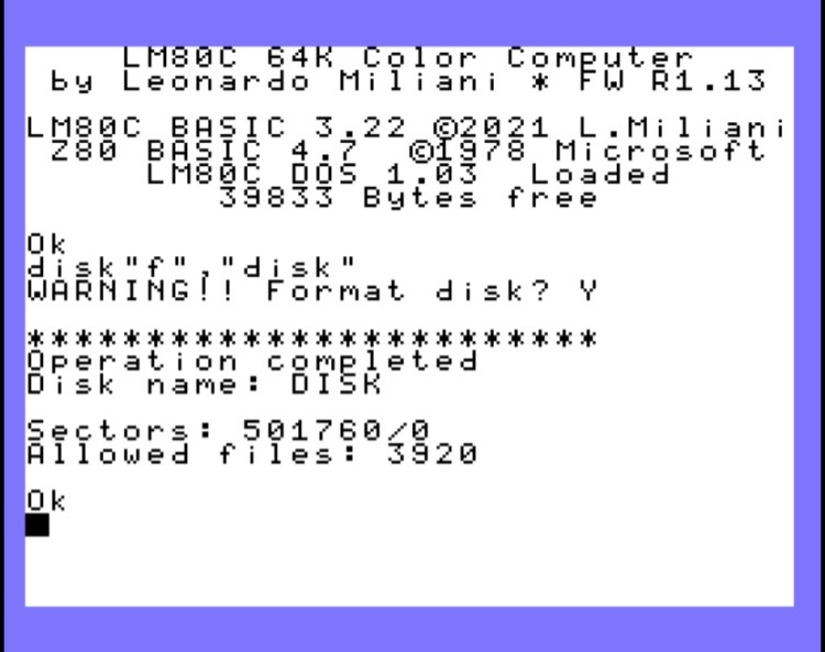
New LM80C DOS 1.03, end, consequently, new firmwares 3.23 and 1.13 for the LM80C & LM80C 64K Color Computers, respectively....
Happy new year and happy new firmwares for the LM80C Color Computers. LM80C: new firmware release 3.16: Code revision to...
Very big XMas news for every fan of my LM80C Z80-based homebrew computer! After some months of development, following the...
Another firmware upgrade, the new R3.15 release introduces a simple yet important feature, the ELSE statement. So, now it is...
Hello everybody. Nice release, today, for the LM80C Color Computer. The new firmware R3.14 comes with an interesting feature: the...
Another firmware release, to fix a minor bug and to implement a new feature: Fixed a little bug in COLOR...
New firmware release 3.13.7: Fixed a bug into the new cursor management routine: now the cursor won’t appear during PRINTing...